
Pagewide Mesh
Head Manifold Filter or Nozzle Guard Mesh
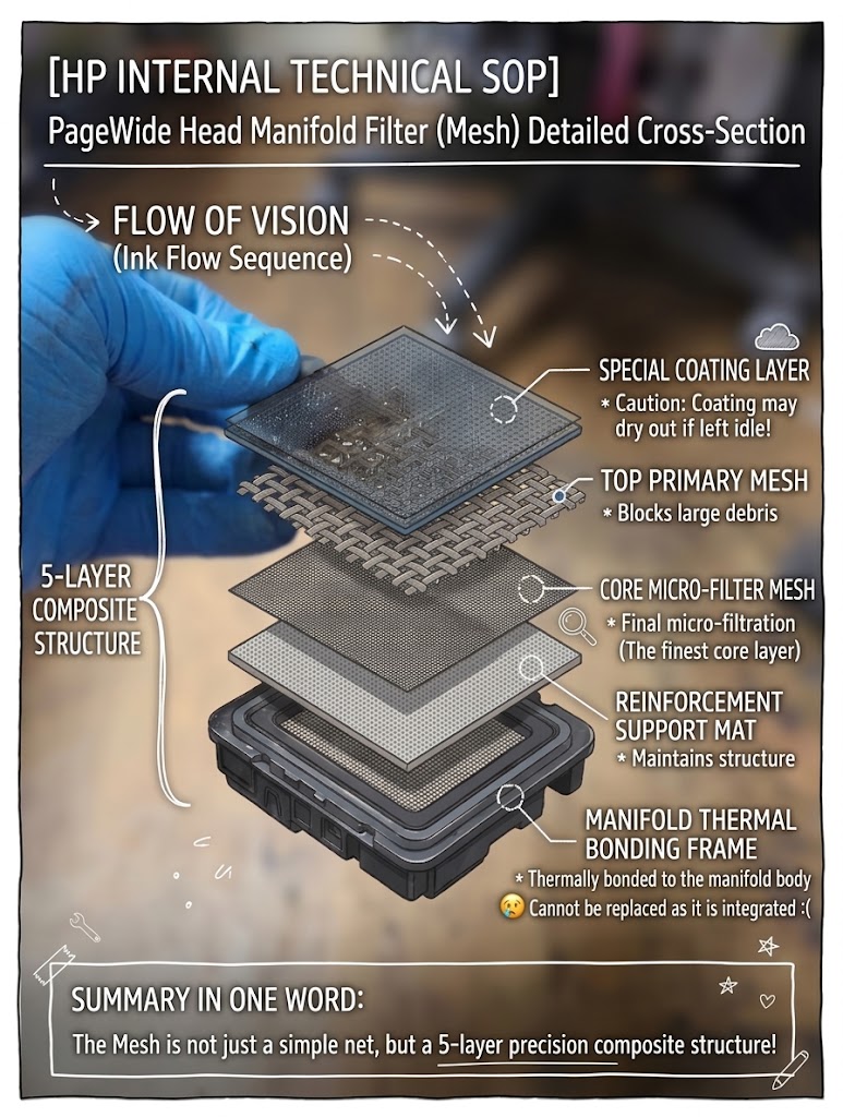
The 'Head Manifold Filter (Mesh)' is not simply a net that filters ink. It is a crucial component that maintains the pressure balance inside the head, integrating Fluid Dynamics and Micro-engineering.
This filter is not just a single layer of net, but a composite structure where 5 layers (5-Layer Composition) with different functions are integrated through a High-Temperature Thermal Bonding method.
-
Micro-level Precision: This mesh consists of microscopic holes that are invisible to the naked eye and is located right above the nozzles. Even an error of 0.01mm during the replacement process causes ink starvation or nozzle clogging.
-
Thermal Bonding Structure: In most HP high-speed heads, this mesh is completely melted and bonded to the plastic chamber body by heat. The moment you attempt to peel it off, the chamber body deforms, making it impossible to attach a new mesh.
-
Clean Environment Required: The inside of the head requires a level of cleanliness similar to a semiconductor manufacturing process. The moment the head is disassembled and the mesh is replaced in a general repair room, fine dust from the air enters the nozzles, causing immediate and permanent damage to the head.
This fine filter, with an overall thickness of only 0.2~0.3mm, consists of:
[Top Section]
-
Layer 1: Special Coating Layer
-
Role: Maintains the wettability of the mesh surface.
-
Description: A special chemical coating that forms capillary pressure and physically blocks the entry of air pockets.
-
-
Layer 2: Top Primary Mesh
-
Role: Blocks large debris and provides structural support.
-
Description: The first layer to welcome the ink, featuring relatively large pores (approx. 100㎛). It primarily filters out large residues.
-
[Core]
-
Layer 3: Core Micro-Filter Mesh
-
Role: Final Micro-Filtration.
-
Description: An ultra-precision mesh with the finest pores around 5-15㎛. It completely filters out fine impurities that could clog the nozzles. (If this layer is blocked, ink will never reach the nozzles.)
-
-
Layer 4: Reinforcement Support Mat
-
Role: Maintains physical structure.
-
Description: A reinforcement layer that firmly supports the fine mesh layers so they are not deformed or torn by water pressure.
-
[Bottom Section]
-
Layer 5: Manifold Bonding Frame
-
Role: Unified Structure.
-
Description: A frame that perfectly seals and fixes the above 4 layers to the head manifold main body using a thermal bonding method. (Because it is a unified structure, replacement is impossible.)
-
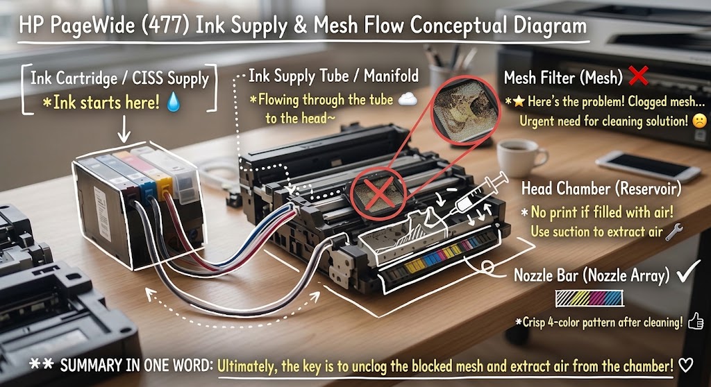
PageWide Mesh Flow Concept
-
Step 1: Ink Supply Source (Ink Cartridge / CISS Supply) When using pigment ink, if left idle for a long time, ink particles begin to settle. For Continuous Ink Supply Systems (CISS), external air inflow or pressure imbalances in the cartridge chip/sub-tank can easily occur.
-
Step 2: Ink Supply Tube and Manifold (Ink Tube / Upper Manifold) If the idle period lengthens, the ink viscosity inside the tube increases, causing the flow rate to drop sharply. If the ink flow is not smooth at this stage, the supply speed to the lower chamber cannot keep up with the nozzle consumption rate.
-
Step 3: Integrated Manifold Mesh Filter (Mesh Filter Area) — [Main Failure Point] When left idle, the special coating on the mesh surface and the ink dry up together, causing a gelling/drying phenomenon. If the fine pores of the filter are blocked, the ink flow path is completely cut off, resulting in a blank printing issue where not a single drop of ink reaches the nozzles. Absolutely NO physical pressure! (If the mesh is damaged, the head must be discarded.) A chemical soaking and dissolving process must be performed by dropping HP official cleaning solution or warm water on the mesh surface and letting it soak for at least 30 minutes to 2 hours.
-
Step 4: Head Chamber and Negative Pressure Formation (Head Reservoir & Pressure Chamber) — [Air Inflow Area] Proper negative pressure must be maintained so that the ink stays ready without flowing out of the nozzles. If printing is attempted while the mesh in Step 3 is blocked or ink is insufficient, a massive air pocket forms inside the chamber. If filled with air, capillary ink transfer becomes impossible. You must closely attach a dedicated suction jig to the nozzle array/suction port at the bottom of the head. Apply negative pressure with a syringe to forcefully extract (Prime) the air and dissolved sediment/cleaning solution out of the chamber, and fill it fully with ink.
-
Step 5: Nozzle Bar and Final Print (PageWide Nozzle Array) This is the core output area of PageWide, where a total of 42,240 fine nozzles for 4 colors are arranged in a row. After the mesh cleaning and chamber suction are completed, execute Printhead Recovery (Level 2~3) from the device's service menu. Print a PQ Diagnostic Page to finally verify if the color nozzle patterns have normalized.
"In the end, the core task is unclogging the blocked mesh and removing air from the chamber!"
If the coating has dried out due to long periods of idleness and the core micro-filter mesh (Layer 3) is completely blocked with ink sediment, this 5-layer composite structure is too fine and precise to physically detach and replace the part by hand.
The only solution is to melt the blocked pores and make them wet with ink again through a 'cleaning and soaking restoration' process using a dedicated cleaning solution and suction jig.
Chemical Cleaning (Soaking & Flushing)
-
Purpose: Melts the hardened ink sediment on the surface and inside the mesh.
-
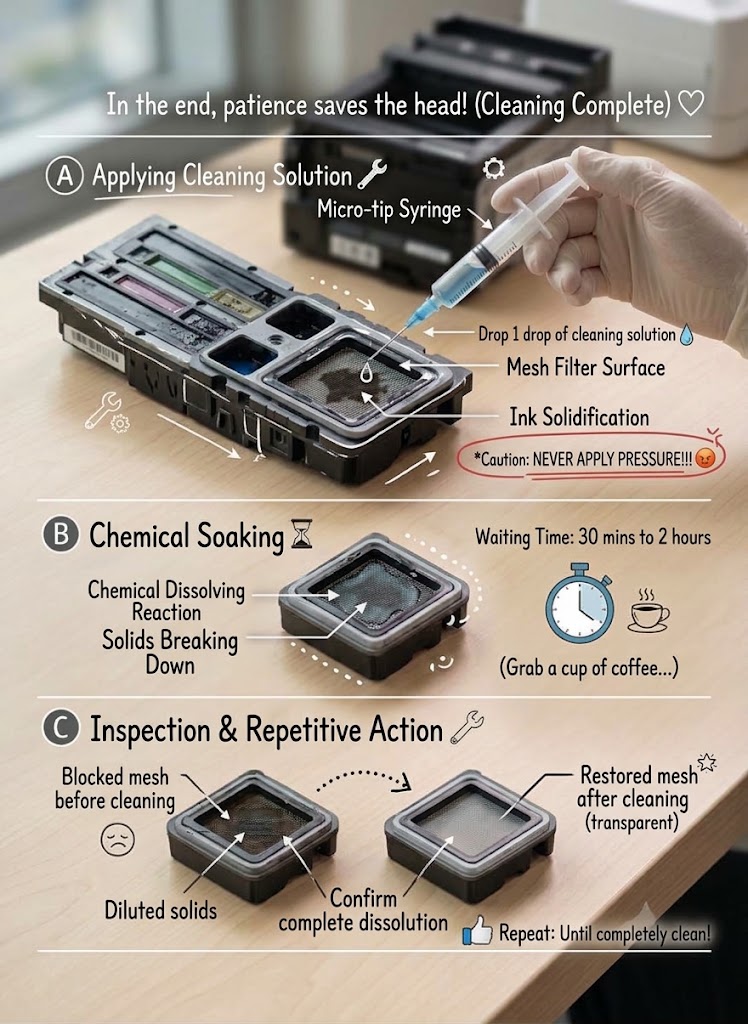
Method: Disassemble the head, drop a small amount of HP official cleaning solution (or dedicated pigment/dye cleaning solution) on the mesh (filter) area, and wait until the ink swells (about 30 minutes to 2 hours). Afterward, gently push and pull (Flushing) the cleaning solution using a syringe and a dedicated jig to extract the impurities.
Engineer's Tip: Never apply excessive pressure. The moment the mesh tears, the head must be discarded.
-
Absolutely NO pressure: The mesh filter is a very delicate tissue. Do not push or shoot the cleaning solution forcefully with a syringe. Only the 'Drop' method using its own weight is allowed. Excessive pressure will tear the mesh tissue, leading to permanent head disposal.
-
Maintain Cleanliness: Before applying the cleaning solution, thoroughly remove dust or debris around the mesh so they do not flow inside along with the solution.
[Caution: The following procedure is a high-risk task that can cause permanent damage to the head.]
-
Step 3-1: Setup cleaning environment and initial drop (Setup & Initial Drop) Disassemble the head and place it horizontally so the manifold filter faces upwards. Fill the syringe with cleaning solution (Prime it so there is no air at the tip). Keep the syringe tip about 2~3mm above the mesh surface, and slowly drop a single drop (around 0.05ml) of cleaning solution to cover the entire mesh surface.
-
Step 3-2: Chemical Soaking Wait until the cleaning solution reacts with the hardened solids on the mesh surface and slowly seeps inside. Waiting time: Depending on the degree of solidification, it can take anywhere from a minimum of 30 minutes to a maximum of 2 hours. Engineer's Tip: During this process, to prevent the cleaning solution from evaporating, it is highly effective to lightly cover the entire head with a sealed container or plastic wrap to maintain humidity.
-
Step 3-3: Condition Check and Repeat Application (Inspection & Repetition) After the waiting period, visually inspect if the color of the cleaning solution on the mesh surface has become cloudy or if the solids have diluted. Drop fresh cleaning solution again over the diluted sediment to accelerate the dissolving reaction. Repeat this process until the solids are completely melted and the mesh tissue looks visually transparent. In severe cases, this may take more than 24 hours.
Add Comment